35+ object diagram software engineering
5 User interfae 4. 2 Class diagrams 3.

Pin On Industrial Engineering
Ad Templates Tools Symbols To Design Any Schematic.
. To control and manage software configuration items each must be separately named and then organized using an object-oriented approach. UML Class Diagram in Software Engineering. In early UML specifications the object diagram is described as.
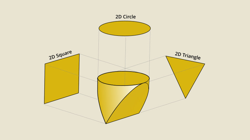
Dutoit 35 Object-Oriented Software Engineering. Two types of objects can be identified. A static object diagram is an instance of a class.
Dynamic changes are not included in the class diagram. In software engineering behavioral model describe the overall behavior of the system. OO Models Slide 1.
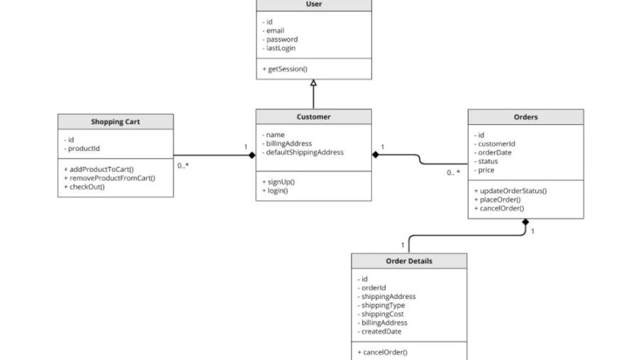
Define the structure of a software system by describing the system classes their attributes and the relationships among them. Object Oriented Models UML GA Software Engineering. Using UML Patterns and Java.
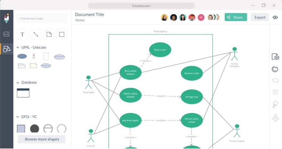
The following UML object diagram example illustrates an instance in a library system. Entity Relationship Diagram aka ERD ER Diagram E-R Diagram is a well-tried software engineering tool for data modeling system design and illustrating the logical structure of. There are five objects in the diagram such as administrator magazine.
Use UML class diagrams to outline the key objects and relationships of the app. Sequence Diagram is a Connection Diagram that represents a single structure or storyline executing in a system. 4 Dynamic models 3.
The class diagram is a model for creating the classes their attributes and functions. There are two types of behavioral models that are used to describe the system behavior one is data. It depicts the static view of a system.
An object diagram is a graph of instances including objects and data values. If you are familiar with classes in OOP then you are the ideal person to understand the class diagram. Glossary Bernd Bruegge Allen H.
The classes in your code and the relationships between then. Minimizes the risks of not delivering a suitable product produces high-quality software that corresponds to the needs of the user. It portrays the real-time behavior of a system.
It is the second most used UML diagram behind the class. For software engineering we need a process that.

Pin On Engineering Drawing 3d
What Is A Uml Diagram And How To Create One 7 Tools

Modern Business Powerpoint Template Business Powerpoint Templates Business Powerpoint Presentation Keynote Template

Integration Of Plant Maintenance Pm With Extended Warehouse Management Ewm In S 4hana 2021 Release Warehouse Management Plant Maintenance Order To Cash

Autocad Shortcut Key Autocad Shortcut Key How To Plan

Java Collection Cheat Sheet Java Tutorial Java Java Cheat Sheet
What Is A Uml Diagram And How To Create One 7 Tools

Active Directory Domain Services Diagram Active Directory Concept Map Diagram

Object Counter Circuit Esquemas Eletronicos Electronics Projects Circuito Eletronico

Exception Hierarchy Diagram Java Oracle Jee Jeee J2ee Jme J2me Jmme Jmee Android Sdk Jdk Java Programming Tutorials Java Tutorial Java Programming Language

Simple Electronic Circuits For Beginners And Engineering Students Simple Electronic Circuits Electronics Circuit Circuit

Pin On Art

Free Editable Spring Data Access Uml Package Diagram Edrawmax Information Visualization Time Diagram Activity Diagram
Unlocking The Innovative Mindset By Geoff Marlow

Mpu 6050 Gyroscope Introduction Teapot 3d Simulation Electric Diy Lab Arduino Projects Arduino Diy Electrical
What Is A Uml Diagram And How To Create One 7 Tools

Pin On 3d Cad Exercises